
Color compositing and color blending
This section shows how GeoServer is able to perform color blending and compositing, either between feature type styles or by associating blending operations with each symbolizer. Either set of operations allows one to control how two overlapping layers/symbols are merged together to form a final map (as opposed to the normal behavior of just stacking images on top of each other).
This section will use the following definitions for the common terms “source” and “destination”:
- Source: Image currently being drawn on top of the map.
- Destination: Background image that the source image is being drawn on.
Specifying compositing and blending in SLD
Composites
Both compositing and blending can be specified in SLD by adding the following VendorOption to either the end of a Symbolizer or FeatureTypeStyle:
<VendorOption name="composite">multiply</VendorOption>In case a custom opacity is desired, it can be added after the operation name separated with a comma:
<VendorOption name="composite">multiply, 0.5</VendorOption>Note
Blending against symbolizers causes exceptions inside the JDK when using OpenJDK. The issue is known and has been reportedly fixed, but only in OpenJDK 9.
One way to get around this issue with OpenJDK 7/8 is to install the Marlin renderer. This replaces the OpenJDK core renderer and does not suffer from the same issue.
Oracle JDK 7 or 8 does not show this issue.
Composites bases
For FeatureTypeStyles an additional vendor option can be added to control compositing groups:
<VendorOption name="composite-base">true</VendorOption>This will tell the rendering engine to use that FeatureTypeStyle as the destination and will compose all subsequent FeatureTypeStyle/Layers on top of it until another base is found. Once the full set of layers against a base is composed, then the base itself will be composed against the next set of composed layers using its own compositing operator, if present.
Without this setting, the destination will be the full stack of all previous FeatureTypeStyles and layers drawn before the current one. This can be limiting for two reasons:
- It limits the usefulness of alpha-composite masking operations
- It breaks the WMS model, where the client can decide freely how to stack layers (the desired compositing effects will be achieved only when a certain stack of layers is used)
Consider the following example:
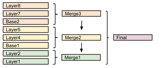
In this example, the first two layers are drawn on top of each other, forming “Merge1”.
The third layer is a composite base, as such it won’t be merged on top of the already drawn map immediately, but it will be drawn to an off-screen buffer, and layer 4 and 5 will be drawn/composited on top of it. Once that happens, “Merge2” is ready, and gets drawn on top of “Merge1”.
The next layer is another base, so “Base2” will be again drawn to an off-screen buffer, and layer 7 and 8 will be drawn/composited on top of it, forming Merge3. Once Merge3 is ready, it will be drawn/composited on top of the already fused Merge1/Merge2, generating the final map.
Composite and blending example
Let’s say we want to draw the
topp:stateslayer so that the polygons are not filled with the population keyed colors, but only an inner border inside the polygon should appear, leaving the internal fully transparent. Using alpha blending, this can be achieved by creating a mask around the state borders with a thick stroke and then using a “destination-in” alpha compositing.The SLD will contain three FeatureTypeStyles. The first one would be the standard rules (states colored by population) and the last one will contain the label rules. The second (middle) one is where the blending will occur:
...
  <FeatureTypeStyle>
    <!-- Usual states rules, skipped for brevity -->
  </FeatureTypeStyle>
  <FeatureTypeStyle>
    <Rule>
      <LineSymbolizer>
        <Stroke>
          <CssParameter name="stroke-width">10</CssParameter>
          <CssParameter name="stroke">#000000</CssParameter>
        </Stroke>
      </LineSymbolizer>
    </Rule>
    <VendorOption name="composite">destination-in</VendorOption>
  </FeatureTypeStyle>
  <FeatureTypeStyle>
    <!-- The label rules, skipped for brevity -->
  </FeatureTypeStyle>
  ...
This table summarizes the composition performed:
Destination Source Result 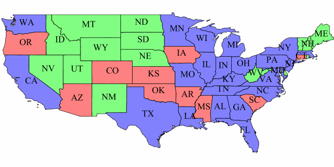
Copy the next SLD definition and add it to geoserver as a new style named
statesblend:<?xml version="1.0" encoding="ISO-8859-1"?> <StyledLayerDescriptor version="1.0.0" xmlns="http://www.opengis.net/sld" xmlns:ogc="http://www.opengis.net/ogc" xmlns:xlink="http://www.w3.org/1999/xlink" xmlns:xsi="http://www.w3.org/2001/XMLSchema-instance" xmlns:gml="http://www.opengis.net/gml" xsi:schemaLocation="http://www.opengis.net/sld"> <NamedLayer> <Name>USA states population</Name> <UserStyle> <Name>population</Name> <Title>Population in the United States</Title> <Abstract>A sample filter that filters the United States into three categories of population, drawn in different colors</Abstract> <FeatureTypeStyle> <Rule> <Name>test</Name> <Title>< 2M</Title> <ogc:Filter> <ogc:PropertyIsLessThan> <ogc:PropertyName>PERSONS</ogc:PropertyName> <ogc:Literal>2000000</ogc:Literal> </ogc:PropertyIsLessThan> </ogc:Filter> <PolygonSymbolizer> <Fill> <!-- CssParameters allowed are fill (the color) and fill-opacity --> <CssParameter name="fill">#4DFF4D</CssParameter> <CssParameter name="fill-opacity">0.7</CssParameter> </Fill> </PolygonSymbolizer> </Rule> <Rule> <Title>2M - 4M</Title> <ogc:Filter> <ogc:PropertyIsBetween> <ogc:PropertyName>PERSONS</ogc:PropertyName> <ogc:LowerBoundary> <ogc:Literal>2000000</ogc:Literal> </ogc:LowerBoundary> <ogc:UpperBoundary> <ogc:Literal>4000000</ogc:Literal> </ogc:UpperBoundary> </ogc:PropertyIsBetween> </ogc:Filter> <PolygonSymbolizer> <Fill> <!-- CssParameters allowed are fill (the color) and fill-opacity --> <CssParameter name="fill">#FF4D4D</CssParameter> <CssParameter name="fill-opacity">0.7</CssParameter> </Fill> </PolygonSymbolizer> </Rule> <Rule> <Title>> 4M</Title> <!-- like a linesymbolizer but with a fill too --> <ogc:Filter> <ogc:PropertyIsGreaterThan> <ogc:PropertyName>PERSONS</ogc:PropertyName> <ogc:Literal>4000000</ogc:Literal> </ogc:PropertyIsGreaterThan> </ogc:Filter> <PolygonSymbolizer> <Fill> <!-- CssParameters allowed are fill (the color) and fill-opacity --> <CssParameter name="fill">#4D4DFF</CssParameter> <CssParameter name="fill-opacity">0.7</CssParameter> </Fill> </PolygonSymbolizer> </Rule> <!-- UNCOMMENT THIS SECTION --> <!--VendorOption name="composite">multiply</VendorOption> <VendorOption name="composite-base">true</VendorOption--> </FeatureTypeStyle> <FeatureTypeStyle> <Rule> <LineSymbolizer> <Stroke> <CssParameter name="stroke-width">10</CssParameter> <CssParameter name="stroke">#000000</CssParameter> </Stroke> </LineSymbolizer> </Rule> <VendorOption name="composite">destination-in</VendorOption> </FeatureTypeStyle> <FeatureTypeStyle> <Rule> <Title>Boundary</Title> <LineSymbolizer> <Stroke> <CssParameter name="stroke-width">0.2</CssParameter> </Stroke> </LineSymbolizer> <TextSymbolizer> <Label> <ogc:PropertyName>STATE_ABBR</ogc:PropertyName> </Label> <Font> <CssParameter name="font-family">Times New Roman</CssParameter> <CssParameter name="font-style">Normal</CssParameter> <CssParameter name="font-size">18</CssParameter> </Font> <LabelPlacement> <PointPlacement> <AnchorPoint> <AnchorPointX>0.5</AnchorPointX> <AnchorPointY>0.5</AnchorPointY> </AnchorPoint> </PointPlacement> </LabelPlacement> <VendorOption name="partials">false</VendorOption> </TextSymbolizer> </Rule> </FeatureTypeStyle> </UserStyle> </NamedLayer> </StyledLayerDescriptor>Note
The CSS equivalent of this style is the following
* {
  z-index: 0;

  [PERSONS<'2000000'] {
    fill: #4DFF4D;
    fill-opacity: 0.7;
  };

  [PERSONS>='2000000' and PERSONS<='4000000'] {
    fill: #FF4D4D;
    fill-opacity: 0.7;
  };

  [PERSONS>'4000000'] {
    fill: #4D4DFF;
    fill-opacity: 0.7;
  };

  /* UNCOMMENT THIS SECTION */
  /* composite: 'multiply';
  composite-base: 'true'; */
}

* {
  z-index: 1;
  stroke: #000000;
  stroke-width: 10;
  composite: 'destination-in';
}

* {
  z-index: 2;
  stroke: #000000;
  stroke-width: 0.2;
  label: [STATE_ABBR];
  font-family: 'Times New Roman';
  font-style: 'normal';
  font-size: 18;
  font-fill: #000000;
  label-anchor: 0.5 0.5;
}
After creating the previous SLD, make the following request:
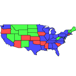
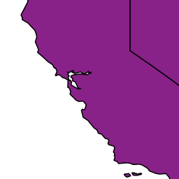
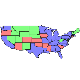
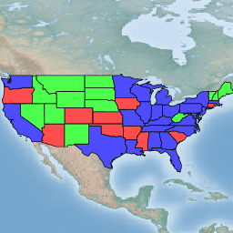
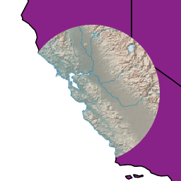
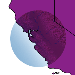
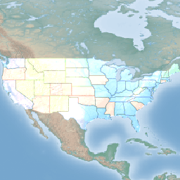
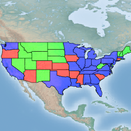
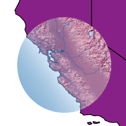
http://localhost:8083/geoserver/geosolutions/wms?service=WMS&version=1.1.0&request=GetMap&layers=geosolutions:states&styles=statesblend&bbox=-124.73142200000001,24.955967,-66.969849,49.371735&width=768&height=330&srs=EPSG:4326&format=application/openlayersThe output should be similar to this image:
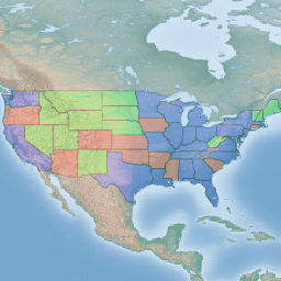
Now perform the following request and zoom in to Colorado state:
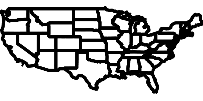
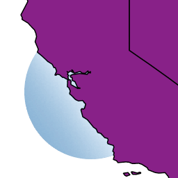
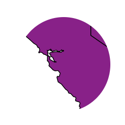
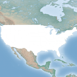
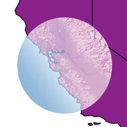
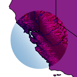
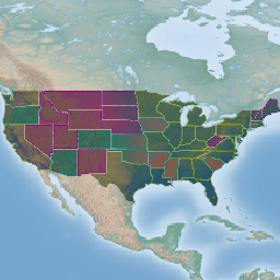
http://localhost:8083/geoserver/geosolutions/wms?service=WMS&version=1.1.0&request=GetMap&layers=geosolutions:Counties,geosolutions:states&styles=,statesblend&bbox=-124.73142200000001,24.955967,-66.969849,49.371735&width=768&height=330&srs=EPSG:4326&format=application/openlayersResult request should be similar to this:
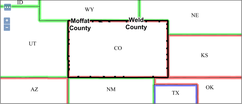
As it can be easily seen the background layer is almost not visible because it has been cut by the mask. In order to achieve background transparency the first FeatureTypeStyle that draws the polygons (the states themselves) needs to be set as a compositing base, ensuring the mask will only be applied to it.
Navigate to styles in Geoserver and open the previously created SLD
statesblend. Locate and change the following lines:... <!-- UNCOMMENT THIS SECTION --> <!--VendorOption name="composite">multiply</VendorOption> <VendorOption name="composite-base">true</VendorOption--> ...Uncomment composite and composite-base vendor options:
...
<!-- UNCOMMENT THIS SECTION -->
<VendorOption name="composite">multiply</VendorOption>
<VendorOption name="composite-base">true</VendorOption>
...
Once done submit the SLD
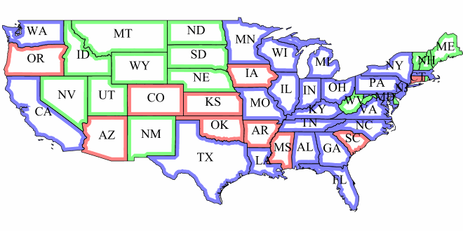
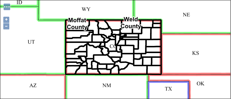
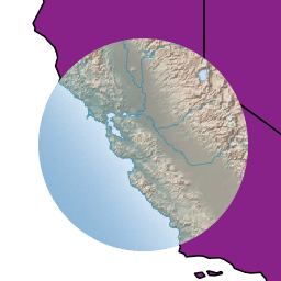
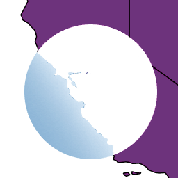
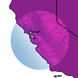
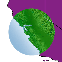
statesblendchange and perform again the same previous request and zoom in to Colorado state:http://localhost:8083/geoserver/geosolutions/wms?service=WMS&version=1.1.0&request=GetMap&layers=geosolutions:Counties,geosolutions:states&styles=,statesblend&bbox=-124.73142200000001,24.955967,-66.969849,49.371735&width=768&height=330&srs=EPSG:4326&format=application/openlayersNote
You might need to use a browser incognito window or clear browser cache in order to avoid returning a cached version of the previous image
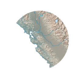
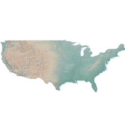
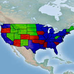
Result request should now reveal the background layer:
Composite and blending modes
There are two types of modes:
- Alpha compositing controls how two images are merged together by using the alpha levels of the two. No color mixing is being performed, only pure binary selection (either one or the other).
- Color blending modes mix the colors of source and destination in various ways. Each pixel in the result will be some sort of combination between the source and destination pixels.
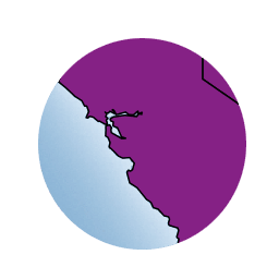
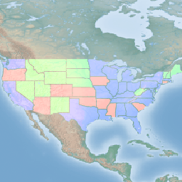
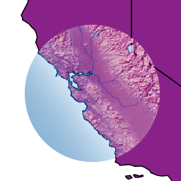
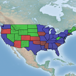
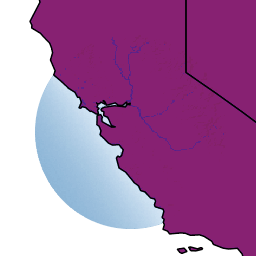
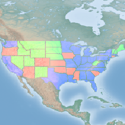
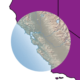
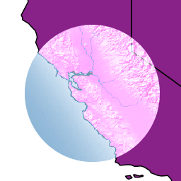
The following page shows the full list of available modes. To aid in comprehension, two source and two destination images will be used to show visually how each mode works:
| Source 1 | Source 2 |
|---|---|
|

|
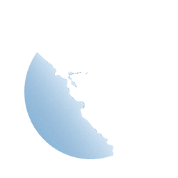
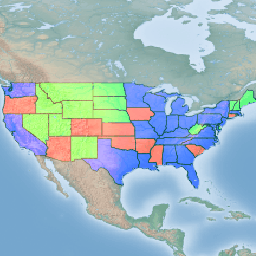
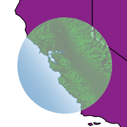
| Destination 1 | Destination 2 |
|---|---|

|
|
Alpha compositing modes


source-over mode
The source is drawn over the destination and the destination is visible where the source is transparent. Opposite of destination-over.
| Example 1 | Example 2 |
|---|---|

|
|
destination-over mode
The source is drawn below the destination and is visible only when the destination is transparent. Opposite of source-over.
| Example 1 | Example 2 |
|---|---|
|
|
source-in mode
The source is visible only when overlapping some non-transparent pixel of the destination. This allows the background map to act as a mask for the layer/feature being drawn. Opposite of destination-in.
| Example 1 | Example 2 |
|---|---|
|
|
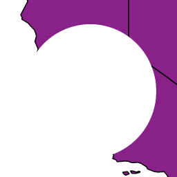
destination-in mode
The destination is retained only when overlapping some non transparent pixel in the source. This allows the layer/feature to be drawn to act as a mask for the background map. Opposite of source-in.
| Example 1 | Example 2 |
|---|---|

|
|
source-out mode
The source is retained only in areas where the destination is transparent. This acts as a reverse mask when compared to source-in.
| Example 1 | Example 2 |
|---|---|

|
|
destination-out mode
The destination is retained only in areas where the source is transparent. This acts as a reverse mask when compared to destination-in.
| Example 1 | Example 2 |
|---|---|

|
|
source-atop mode
The destination is drawn fully, while the source is drawn only where it intersects the destination.
| Example 1 | Example 2 |
|---|---|
|
|
destination-atop mode
The source is drawn fully and the destination is drawn over the source only where it intersects it.
| Example 1 | Example 2 |
|---|---|
|
|
xor mode
“Exclusive Or” mode. Each pixel is rendered only if either the source or the destination is not blank, but not both.
| Example 1 | Example 2 |
|---|---|
|
|
Color blending modes
multiply mode
The source color is multiplied by the destination color and replaces the destination. The resulting color is always at least as dark as either the source or destination color. Multiplying any color with black results in black. Multiplying any color with white preserves the original color.
| Example 1 | Example 2 |
|---|---|
|
|
screen mode
Multiplies the complements of the source and destination color values, then complements the result. The end result color is always at least as light as either of the two constituent colors. Screening any color with white produces white; screening with black leaves the original color unchanged.
The effect is similar to projecting multiple photographic slides simultaneously onto a single screen.
| Example 1 | Example 2 |
|---|---|
|
|
overlay mode
Multiplies (screens) the colors depending on the destination color value. Source colors overlay the destination while preserving its highlights and shadows. The backdrop color is not replaced but is mixed with the source color to reflect the lightness or darkness of the backdrop.
| Example 1 | Example 2 |
|---|---|
|
|
darken mode
Selects the darker of the destination and source colors. The destination is replaced with the source only where the source is darker.
| Example 1 | Example 2 |
|---|---|
|
|
lighten mode
Selects the lighter of the destination and source colors. The destination is replaced with the source only where the source is lighter.
| Example 1 | Example 2 |
|---|---|
|
|
color-dodge mode
Brightens the destination color to reflect the source color. Drawing with black produces no changes.
| Example 1 | Example 2 |
|---|---|
|
|
color-burn mode
Darkens the destination color to reflect the source color. Drawing with white produces no change.
| Example 1 | Example 2 |
|---|---|
|
|
hard-light mode
Multiplies or screens the colors depending on the source color value. The effect is similar to shining a harsh spotlight on the destination.
| Example 1 | Example 2 |
|---|---|
|
|
soft-light mode
Darkens or lightens the colors depending on the source color value. The effect is similar to shining a diffused spotlight on the destination.
| Example 1 | Example 2 |
|---|---|
|
|
difference mode
Subtracts the darker of the two constituent colors from the lighter color. White inverts the destination color; black produces no change.
| Example 1 | Example 2 |
|---|---|
|
|
exclusion mode
Produces an effect similar to that of difference but lower in contrast. White inverts the destination color; black produces no change.
| Example 1 | Example 2 |
|---|---|
|
|