
Geometry transformations
This section shows how GeoServer provides a number of filter functions that can actually manipulate geometries by transforming them into something different: this is what we call geometry transformations in SLD.
Extracting vertices
Using skills learned in the adding styles section, create a new style named mainrd_transform using the following SLD:
<?xml version="1.0" encoding="ISO-8859-1"?>
<StyledLayerDescriptor version="1.0.0"
  xmlns="http://www.opengis.net/sld" xmlns:ogc="http://www.opengis.net/ogc"
  xmlns:xlink="http://www.w3.org/1999/xlink" xmlns:xsi="http://www.w3.org/2001/XMLSchema-instance"
  xsi:schemaLocation="http://www.opengis.net/sld http://schemas.opengis.net/sld/1.0.0/StyledLayerDescriptor.xsd">
  <NamedLayer>
    <Name>Roads and vertices</Name>
    <UserStyle>
      <FeatureTypeStyle>
        <Rule>
          <LineSymbolizer>
            <Stroke />
          </LineSymbolizer>
          <PointSymbolizer>
            <Geometry>
              <ogc:Function name="vertices">
                <ogc:PropertyName>the_geom</ogc:PropertyName>
              </ogc:Function>
            </Geometry>
            <Graphic>
              <Mark>
                <WellKnownName>circle</WellKnownName>
                <Fill>
                  <CssParameter name="fill">#FF0000</CssParameter>
                </Fill>
              </Mark>
              <Size>6</Size>
            </Graphic>
          </PointSymbolizer>
        </Rule>
      </FeatureTypeStyle>
    </UserStyle>
  </NamedLayer>
</StyledLayerDescriptor>
Note
The CSS equivalent of this style is:
* {
  mark: symbol(circle);
  mark-geometry: [vertices(the_geom)];
  mark-size: 6;
  stroke: #000000;
  :nth-mark(1) {
    fill: #FF0000;
  }
}
Note
The
verticesfunction returns a multi-point made with all the vertices of the original geometryThen, modify the styling of the
Mainrdlayer and addmainrd_transformas an alternate style (hint: select themainrd_transformstyle in the first list below “available styles” and then use the right arrow to move it in the “selected styles”):
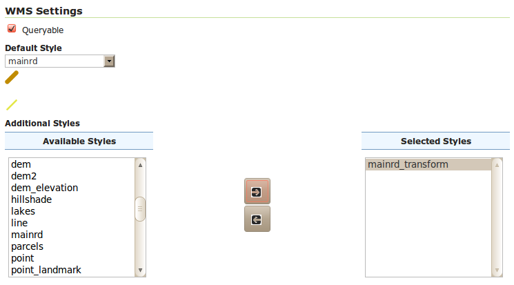
Adding the mainrd_transform style as a secondary style for Mainrd
Use the Preview link to display the Mainrd layer, then open the options box and choose the alternate style from the drop down:
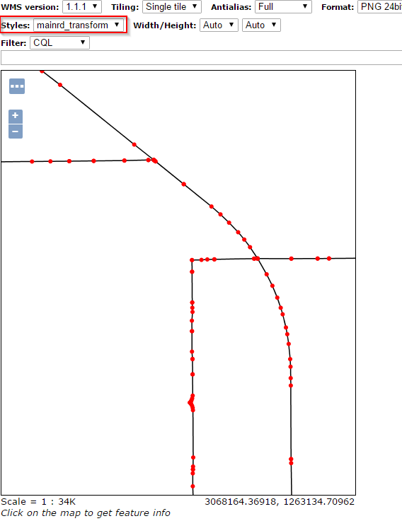
Extracting and showing the vertices out of a geometry
Line buffer
Using skills learned in the adding styles section, create a new style mainrd_buffer using the following SLD
<?xml version="1.0" encoding="ISO-8859-1"?>
<StyledLayerDescriptor version="1.0.0"
xmlns="http://www.opengis.net/sld" xmlns:ogc="http://www.opengis.net/ogc"
xmlns:xlink="http://www.w3.org/1999/xlink" xmlns:xsi="http://www.w3.org/2001/XMLSchema-instance"
xsi:schemaLocation="http://www.opengis.net/sld http://schemas.opengis.net/sld/1.0.0/StyledLayerDescriptor.xsd">
  <NamedLayer>
    <Name>Roads and vertices</Name>
    <UserStyle>
      <FeatureTypeStyle>
        <Rule>
          <PolygonSymbolizer>
            <Geometry>
              <ogc:Function name="buffer">
                <ogc:PropertyName>the_geom</ogc:PropertyName>
                <ogc:Literal>200</ogc:Literal>
              </ogc:Function>
            </Geometry>
             <Fill>
              <CssParameter name="fill">#7F7F7F</CssParameter>
              <CssParameter name="fill-opacity">0.3</CssParameter>
            </Fill>
          </PolygonSymbolizer>
          <LineSymbolizer>
            <Stroke />
          </LineSymbolizer>
        </Rule>
      </FeatureTypeStyle>
    </UserStyle>
  </NamedLayer>
</StyledLayerDescriptor>
Note
The CSS equivalent of this style is:
* {
  stroke: #000000;
  stroke-opacity: 1.0, 0.0;
  fill: #7F7F7F;
  fill-opacity: 0.0, 0.3;
  fill-geometry: [the_geom], [buffer(the_geom, 200)];
}
Note
The
bufferfunction builds a polygon of all the points that are within the specified distance from the original geometry.As done previously, modify the styling of the
Mainrdlayer and addmainrd_bufferas an alternate style:
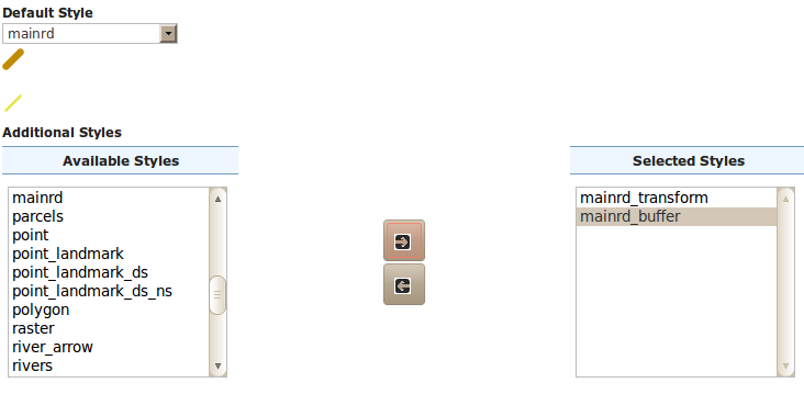
Adding the mainrd_buffer style as a secondary style for Mainrd
Use the
Map Previewto preview the new style.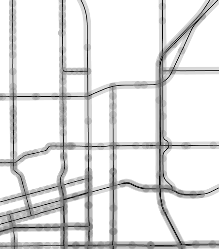
Extracting start and end point of a line